Sunday, October 11, 2020

AVR-IOT WG DEVELOPMENT BOARD

 AVR-IOT WG DEVELOPMENT BOARD


Introductions:


Requirements:

Objectives:


Methodology:


Summary:

Conclusions:


Monday, November 18, 2019

Micro Lidar + ROS + Arduino


Introductions :


Objectives:


Requirements:

Methodology:


Summary :


Conclusions:

2WD/4WD ROS Controller Board


Introduction:
This controller board is 


Objectives:


Requirements:


Methodology:


Procedures


Summary:


Conclusions:

Tuesday, April 3, 2018

NanoPi ROS (NanoPi NEO Plus 2 + Robotic Operating System)


Introduction:
Hello, here we are once again to tackle a very interesting topic- this time its about a single board computer which  will be sufficient in compiling  and running the entire package of Robotic Operating System (ROS) . I have given some times to figure out a kind of single board which has a power of computing ,enough memory (RAM)  and GPU ready to lower the production price of our robots. To date, I see some failures posted on the internet that NanoPi M3 wasn't working with ROS my sympathy to them for the so called  problem that lost their appetite and to totally ignore the board's potential. So, I urge my self a second opportunity of exploiting the problem and  how to test NanoPi. If this board doesn't really work well on R.O.S then   there is no doubt that it would have a "not good" impression(?) since the board was not so popular with the rest of the SBC brands in the market. I would charge it on my own technical experiences , for the benefit of the doubt so lets then give it a try.

So why NanoPi NEO Plus 2? Of course one simple answer is that I have tested it running other than that there is no reason choose this nano computer to be posted here. NanoPi  SBC only cost 24$ , ran on a 64 bit mode  of quad-core processor , can store data of 1GB DDR3 in its RAM including  LAN and Wifi as its features. Compared to other single board computer in the market its price will really entice hobbyist for their robots. Comparing performance and cost will definitely give an advantage to this board to have a priority on imaging with  ROS. A sort of  computer platform with considerable performance and price it is worth than not trying it.

I would like to thank the linorobot(Juan Miguel Jimeno)  community for this guidelines and other folks who are eager to contribute for  learning,teaching and  experimenting ROS for the geeks. Also , we want to promote Philippine Society of Computer Engineering through out the country and most of founders are Oragons. So much inspiration why we keep striving to cope-up with the global robotics . PSCoE  believes its not too late to go with the race  now and soon we are happy and we are heading further than our expectations.

Thank you guys!  

Requirements:
Hardware:
NanoPi NEO PLUS 2
LAN Cable
Laptop/Desktop

Softwares:
Ubunto 16.04
ROS (kenetic)


Methodology:

1) We need to follow the steps on installing an image to NanoPI NEO Plus 2, in our installation here we preferred the Ubuntu-16.04-xenial-core
Link:
https://drive.google.com/drive/folders/1Yj3tXryBx6zksOOuTlm2iOT-IDSzUTTe

2) Please activate both LAN and WiFi Network communications, see to it that they can communicate each other in the network , so you may use ssh,ping and etc.

Link:
http://wiki.friendlyarm.com/wiki/index.php/NanoPi_NEO_Plus2

3) Lets us now copy some ROS installation guide, or you can compile all these command lines into  a file  script

3.a) Install dependencies
pi#   sudo apt-get update
pi#   sudo apt-get upgrade
pi#   sudo apt-get install -y avahi-daemon
pi#   sudo apt-get install -y openssh-server
pi#   sudo apt-get install -y python-setuptools
pi#   sudo apt-get install -y python-dev
pi#   sudo apt-get install -y build-essential
pi#   sudo apt-get install -y python-gudev


3.b)  Install ROS package
pi#   sudo sh -c 'echo "deb http://packages.ros.org/ros/ubuntu $(lsb_release -sc) main" > /etc/apt/sources.list.d/ros-latest.list'
pi#   wget http://packages.ros.org/ros.key -O - | sudo apt-key add -
pi#   sudo apt-get update
pi#    sudo apt-get -y install ros-kinetic-ros-base
pi#    sudo apt-get install python-rosdep -y
pi#    sudo `which rosdep` init
pi#    rosdep update

pi#    rosdep install --default-yes --from-paths . --ignore-src --rosdistro kinetic
pi#    source /opt/ros/kinetic/setup.bash
pi#   export PYTHONPATH=$PYTHONPATH:/usr/lib/python2.7/dist-packages

pi#   echo "source /opt/ros/kinetic/setup.bash" >> ~/.bashrc
pi#   source ~/.bashrc

3.c) Install ROS libraries
pi#    source /opt/ros/kinetic/setup.bash
pi#    sudo apt-get install -y ros-kinetic-roslint
pi#    sudo apt-get install -y ros-kinetic-rosserial
pi#    sudo apt-get install -y ros-kinetic-rosserial-arduino
pi#    sudo apt-get install -y ros-kinetic-imu-filter-madgwick
pi#    sudo apt-get install -y ros-kinetic-gmapping
pi#    sudo apt-get install -y ros-kinetic-map-server
pi#    sudo apt-get install -y ros-kinetic-navigation


3.d) Install ROS available sensors libraries(LIDAR and cameras)
pi#      sudo apt-get install -y ros-kinetic-xv-11-laser-driver   
pi#      sudo apt-get install -y ros-kinetic-freenect-launch
pi#      sudo apt-get install -y ros-kinetic-depthimage-to-laserscan
pi#      sudo apt-get install -y ros-kinetic-realsense_camera
pi#      sudo apt-get install -y ros-kinetic-depthimage-to-laserscan


4) Create a catkin workspace(xentrinobot is just my own robot's alias)
pi#   mkdir -p xentrinobot_ws/src
pi#   cd xentrinobot_ws/src
pi#   catkin_init_workspace


4.a) enter your catkin development inside this workspace
pi#   cd ~/xentrinobot_ws
pi#   catkin_make  -j2
pi#   source devel/setup.bash
pi#   echo "source ~/xentrinobot_ws/devel/setup.bash" >> ~/.bashrc
pi#   source ~/.bashrc


5)Connect  NanoPi from your Computer(PC)
pi# ifconfig
pi#  ssh pi@192.168.8.4
Use ROS between NanoPi and your PC

5.a) First, set IP Address to set hosts name.Then  edit the file /etc/hosts with some editor.
pi#  sudo vi /etc/hosts

5.b)Add these two lines and save it.
192.168.8.4  NanoPi
192.168.8.5  MyComputer

Note: This is just an example please change it as to what IP addresses that you have.

5.c) Check if the hosts is right by using ping

p# ping NanoPi

Please run roscore at NanoPi , in this example we use NanoPi as our computer on-boarded in a robot so it initialize as a master.  Before starting roscore, export to ROS_HOSTNAME and ROS_MASTER_URI

p#   export ROS_HOSTNAME=NanoPi
pi#  export ROS_MASTER_URI=http://NanoPi:11311
pi#  roscore

5.d)  Then, using your developmental computer, export to ROS_HOSTNAME and ROS_MASTER_URI in your PC
robook# export ROS_HOSTNAME=MyComputer
robook# export ROS_MASTER_URI=http://NanoPi:11311

5.e) Now, you can see rostopic of NanoPi
robook# rostopic list
/chatter
/rosout
/rosout_agg


Remarks:

0) If some errors occur , please try to look a missing package that are need to be installed or compile.

1)  if using a single board computer please make a lesser thread during the catkin compilation "catkin_make -j 2 , one or two threads will do for that purpose.

2) If catkin_make is not recognize , try to use source /devel/setup.bash for its workspace initialization

3) For RPLIDAR undetected usb/serial port , possible issue is the un installed usb driver ( https://www.silabs.com/documents/public/release-notes/Linux_CP210x_VCP_3.x.x_4.x.x_Release_Notes.txt)

Try this link with your verified e-mail :
pi#   sudo apt-get install libusb*
pi#  wget https://www.silabs.com/documents/login/
software/Linux_3.x.x_4.x.x_VCP_Driver_Source.zip


3.a)  Support for the CP2010N

NOTE:
This driver is an example of how to perform GPIO operations within the CP210x driver since the driver on kernel.org does not support GPIO at this time. This driver has only been written and tested on the Linux 3.13.0 kernel on Ubuntu 14.04. This driver is a modified version of the existing driver in the Linux 3.13.0 kernel, which is maintained at kernel.org. It is recommended to use the driver there that matches your specific kernel version: www.kernel.org

3.b) Build instructions:
Ubuntu:
1. make ( your cp210x driver )
2. cp cp210x.ko to /lib/modules//kernel/drivers/usb/serial
3. insmod /lib/modules/4. insmod cp210x.ko

3.c) GPIO example:
This shows how to use the two IOCTLs to set GPIO state.

3.d) Build instructions:
1. g++ cp210x_gpio_example.c -o cp210x_gpio_example
2. ./cp210x_gpio_example


Summary:

Conclusion:

IOT Embedded boards are used also in ROS
NanoPi Boards are no joke


Monday, March 13, 2017

Arduino Starter kit (K12 STEM)


Arduino RFID Kit

UNANG  KABANATA


Mga pangunahing talata
        Magandang pagkakataon sa lahat ng mga nagbabasa sa blog na ito dahil sa  ngayun ay minabuti ng inyong lingkod na magsulat patungkol sa wastong pagamit ng RFID training kit. Ang kit na maaring nyong gamitin para mapag aralan ang pag buo ng sirkito ng ibat ibat pyesa,modules sa electronics ng Arduino Microcontroler kit. Mahalaga ang kit na ito para sa mga nagnanais na matuto ng Electronic Circuits, Microcontroller Programming at Digital Design, na maari ring pakinabangan sa iba pang application para sa mga project  sa highschool .Ang panimulang kaalaman sa Arduino kit ay may natatanging gamit din tulad halimbawa sa Digital design, robotics at iba pang mga  inmportanteng interface at simulation sa computer. Para maging madali ang mga gagawing hakbang para matutunan ito, kinakailangan malaman at maintindihan ang mga nakalistang kagamitan para mainam na maisagawa ang mga nasabing experimento.
     Ang layunin ng blog na ito ay upang makapag ambag ng kaalaman sa abot makakayang teknical na mensahing maipapaunawa sa mga taga subaybay. Isa na sa mga ito ang grupo ng ating mga kaguruan at mag aaral sa antas ng K11 at K12, ito ay tumutukoy sa STEM na kanilang pag aaralan ay makatuong at magamit ang Arduino para lubos na maintindihan ng ating mga kasamang kabataan ang tulay sa pagawa ng makabagong teknolohiya .

Sya nawa :)


                                  PANGALAWANG KABANATA

Mga kinakailangan
Fritzing Circuit Simulator ang software na kakailanganin sa pag desinyo at pag lalarawan ng mga circuito halimbawa na ang mga koneksyun at pag kakabit kabit ng mga pyesa sa arduino.Sa link na ito maaring ma download ang software   
http://fritzing.org/download/

Arduino IDE ay ang software na gagamtin natin para maisulat at pagnahin ang program.May dalawang pag pipilian para magamit ang software : pwede itong i-install sainyong computer o kaya sa online pwede ng mag compile ng inyong soure code(program)
https://www.arduino.cc/en/Main/Software

Arduino UNO Starter o  RFID Training kit, ang kabuohang ng mga  pyesang gagamitin sa pag buo ng isang experimento sa

Arduino Starter Kit


                                 PANGATLONG KABANATA
                      (Mga kagamitan  sa pagbuo ng proyektong  oCirkito)


Arduino UNO R3   ito ang maliit-na controller or micro-controller ,isang electronic na pyesa na pumapareho sa sa functionalities ng ordinaryong kompyuter. Bagaman walang makikitang monitor ,keyboard ,mouse at ano mang parte katulad ng ordinaryong Kompyuter,  ang isang pag kakatulad nito ay pwede itong malagyan ng -program .Kung may software na ginagawang program sa Kompyuter , may firmware naman sa micro-controller. Ang firmware ay ang program na isinalin sa lenguahe na maiintindihan ng elektronic na makina isa na dito ang maliit na controller -Arduino UNO. Ang firmware ay may pasunod sunod na mga kautusan para magamit ang mga port na terminal  halimbawa ipasok ang signal o ilabas ang signal sa mga pin terminal nito na kung susuriin ay pwedeng may voltahe or wala.    


7 segment display
Seven segment Display  , ang pitong segment na ito ay maliit na butil ng ilaw na kung nabubo nagkakaroon ng hugis numero. Dahil dito sa ganitong resulat , maari na tayong gumawa ng program para maipakita ang mga numerong kumokurte sa ilaw. Isa sa mga gamit nito ang mga palamuti sa pag dispay ng pag bibilang o counter .Madalas natin itong makita  sa mga banko na nag aayos ng mga hanay ng mga customer nila para sa isang transaksyun sa pag iimpok.      


Variable Resistor
Vaiable Resistor  , ay isang pyesang kaparehas ng gamit ng resistor maliban na lang sa kakayahan nito na magkaroon ng ibat ibang  resistance ng isang  cirkito.Maitutulad ito sa dalawa o higit pang nakakabit na mga resistor , na sa bawat pag pihit ay magkakaroon ng pag liit o pag laki ng resistensya nito sanhi ng pag babago sa pag daloy ng kuryento sa isang dugtungan ng cirkito. Adhustable o nababago ang  resistance  depende sa biasing o pag titimpla sa kuryenteng kinakailangan ikarga o ilagay sa isang cirkito. Halimbawa kung ang kakayahang resistensya nito sa kuryente ay simula sa wala o singkwenta 0 to 50 ohms , pwede dito ang laki o liit na umaayon sa wala o limampong kayang resistensyang maibibigay nito para baguhin ang pagdaloy ng kuryento sa isang cirkito. 

                          
Resistor
Resistor  , isa sa gamit at epekto ng pyesang ito ay ang limitahan ang dumadaloy na kuryente o voltahe sa cirkito. Ang uri ng materiales sa pyesang ito  nag hahadlang at nag pipigil para tumakbo ang butil ng mga electron sa loob nito. Sa ganitong pang yayari nababawasan ang anumang lakas nd electrisidad sa kinakabitan nitong cirkito. Gamit ito sa maayos na pag babahagi ng kuryente o pag palakas naman sa voltahe maikakabit dito.Walang itong polarity , pwede dumaloy ang electron dito sa anumang direksyun , subalit ang kakakayahan nitong pumigil ng daloy ng kuryente ay sya ring mapanganib kapag hindi ito masyadong sumakto  o mali ang calkulasyon ng color coding nito.Dahil pumipigil sya sa kuryente at kung magkakamali sa bilang ng resistance nito ay maaring magkasanhi ng pag init o pag kasunod ng pyesa. 

Capacitor
Capacitor  , ang pyesang ito ay may capasiad o kakayahang kumrga ng voltahe at kuryent galing sa sa isang elektric source nito. Dahil sa uri ng sangkap sa pag kakabuo ng semi-conductor na ito (isang pyesang kinakailangan ang isang elektrisidad para  gumana ito ). Sa kadahilanang ito , ang pag kakarga nya ng enerhiya o lakas ng kuryente o voltahe , nagagawa nitong panatilihin ang kinakailangang lakas sa isang cirkito. Subalit depende sa klase ng gamit nito na kung minsan kailangan suriin ang polarity ng koneksyun nito na katulad din ng isang baterya. Anumang kamalian ng + positive o -negative na pin terminal nya ay mag sasanhi ng pagkasira nito at ang iba pa mismong nakakabit dito, maaring masunog o sumabog ito ,kaya kailangan talagang masuri muna ang uri ng kapasitor na gagamitin o ikokonekta sa cirkito 
Breadboard

Breadboard ito ang isang kagamitan kung papano unang binubuo ang pag plano o pag desinyo ng cirkito. Madami itong nakahanay na maliit na butas ,dito ipinapasok ang mga kawad para maikabit kabit ang naitanging koneksyun. Isa sa mga bentahe o lamang na pagamit nito ay madaliang pag buo at pag kalas ng disenyo ng circuito. Nakakatipid din ito sapagkat di na kailangan maghinang ng mga kawad para maisakatuparan ang magiging resulta inaasam sa cirkito. Sa ganitong pag kakataon, kinakailangan natin ang experimental board o breadboard dahil sa mag pag aaral natin sa kit na ito.
                          
Dupont jumper wire
Kawad   ito ay ginagamit na linya ng koneksyun  ng isang elektronik na pyesa kung papaanong ikinakabit sa iba pang  pyesa o parte ng cirkito. May iba-iba itong haba lapad at laki na naaayun sa kinakaliangan gamit , pakakatandaan na habang lumalaki ang kuryente lumalaki din  dapat ang hibla nito . Sa ganitong setup malabis nating gamiting ang dupont wire na makikitang sa larawan.                     


Buttons

Buttons isa ang pyesang ito sa palaging magagamit sa pag
experimento ng ating mga gagawing cirkito. Ang isa sa gamit ng buttones na ito ay ang pag kakaroon ng kontak o koneksyun kapag ito ay na pipindot or na pi-pisil(press). Samakatuwid pwede nating i apply o magamit  ang isang signal sa isang konkesyun na gusto nating ikabit o ilagay sa isang actibong pyesa ia na dyana ng maliit na controller o Arduino UNO.Marami ang ibat ibang disenyo nito , maaring sa kulay , laki at hugis din. Kung mapapansin natin ito ay may mahigit dalawa pang paa , depende sa kung ilang koneksyun ay kaya nyang pagdutungin .                   


                                           PANG APAT NA  KABANATA
                                                           
Mga pamamaraan:
 Saro) Kumpletuhin dapat muna ang mga pyesang mga kinakailangan sa project experiment.Mas mainam din na pag aralang mabuti ang mga kuniksyon polarity (+ - GND) ng bawat pin o terminal ng pyesa. Ito ay nasa drawing ng Fritzing  simulator o kaya sa schematic diagram na planong bubuin.

Duwa) Sa pag program,  maari na lamang munang gamitin ang  mga  source code na gamit halimbawa sa mga gagawing experimento.Ito ay kasama na sa Arduino Software kapag na install na.

Tulo) At kapag gumana na ang program maari na itong tipakin o baguhin ayun sa  gusto kalalabasan ng ating experimento o dili kaya ang desinyo ng ating proyekto.


                                       PANGLIMANG  KABANATA
                                                                 (Mga Pangunahing Pyesa sa Elektronik )
Mga gagawing project sketch:
I) Ang pag papailaw ng LED  at pag papatunog sa  Buzzer

Saro) Tamang koneksyun ayun sa schematic diagram


Duwa)Pag gamit ng source sa halimbawa ng Arduino Softwares


 Tulo)Pag titipak o pag debug para sa ibang output ng program


Apat)  Sa pagtatapos ng proyetktong ito,kinakailangan matutunan ang mga sumusunod.

-Tamang polarity o  signal ng supply na galing sa Arduino ang GRND (-) at VCC ang (+) na syang pag kakabitan ng dalwang kawad ng LED.Kailangan ito para di masira ang Arduino at ang LED dahil kapag magkaiba o baliktad ito ay magsasanhi ng pag init na ikakasira ng alinmang pyesa magkakabit.
-Ang pag pili ng sample code na kasama na sa software ng  arduino
-Ang tamang pag tuklas sa kaayusan(data structure) at pag sunod sunod(algorithm) ng  program.Ang kakayahang baguhin source code para mapag aralan ang mga ibat ibang maaring  kalalabasan ng program ito ay literal na makikita sa ibat ibang pagpatay at sindi ng ilaw.


II) Ang pag patunog ng  buzzer,
Saro) Sa susunod na proyektong ito , ay kailangan lang mapag aralan ang pag kabit ng buzzer sa terminal ng arduino at ito ay walang pinagkaiba sa pinagkaibitan ng LED.

Duwa) Katulad ng dating source code sa experimento sa pag pa blink ng LED

Tulo) Katulad ng pag babago ng source code sa pag papailaw ng  LED

Apat) Parehong anaylisis .


                                       PANGANIM NA KABANATA
                                                              (Mga actuator at motor )

III) Pag papaikot sa Motor , sa stepper motor at servo motor

Servo motor(may  feedback)


 DC motor(walang feedback)


IV) Ang pagpaikot sa stepper motor, ito ang motor na umiikot alinsunod sa pulso ng signal o voltahe. Ang pa bugso bugso lakas ng kuryente at boltahe na nag bibigay pwersa para ito umikot clockwise o kabalitan na ikot.


Saro)Mapapansin ang nakakaibang dami ng wires na nakakabit sa stepper motor, at ito ay naiiba sa pangkaraniwang koneksyun ng ordinaryong motor lamang.Pansin ang mga kinakabitan ng kawad galing sa arduino  at stepper motor.


Duwa)


Tulo)


                                     PANGPITONG KABANATA
                                                              (Mga analog at digital na sensors )


V)Sensor sa pagsukat ng halumigmig at temperatura ng isang bagay.
Ang DHT11 ay ang pyesang kasama sa kit na magagamit para masukat
kung gaano mamasa masa at kainit ang isang spasyo o bagay

Saro)Tiyakin ang pag kakabit ng sensor sa kawad tungo sa header pin ng arduino


Duwa)Mapansin nyo ang mga pins na nag bibigay ng tanda kung saan ang kawad ng sensor ay ikakabit sa pin ng arduino


Tulo)Simpleng pag babago lang sa katumbas na bilang ng antala sa pag basa
ng tanging halumigmig at temperatura


Apat)  Sa pagtatapos ng proyetktong ito,kinakailangan matutunan ang mga sumusunod:

-Tamang pag kakabitan ang kawad ng DHT sensor.Kailangan ito para matiyak na maayos na dadaloy ang signal para mabasa ng Arduino ang data sa DHT module.
-Ang pag pili ng sample code para sa sensor na kasama na sa software ng  arduino
-Ang tamang pag tuklas sa configuration ng pin o terminal.Ang kakayahang baguhin source code para mapag aralan kung paano katiyak  o kahalaga ang mga bilang na mababasang maglalarawa sa lakas o hina ng temperatura at halumigmig.


                                 PANG WALONG KABANATA
                                                              (Mga palarawan o display  )

VI) Ang pagamit ng Liquid Crystal Display o LCD sa pag display ng output na literal na makikita sa screen nito. May laki at dami ng mga letrang alphabets ang kaya nitong ipakita na sapat sa screen nito. Ang modelo ng LCD ay 16x2  ito ay may dalawangpo na letra (20 characters) sa bawat hilera(row) na idi-display.
Saro) Ang schematic ng LCD 16x2 at ng Arduino.


Duwa)


Tulo)

VII) Ang pagamit ng Dot Matrix, ito ay isa na namang pyesa para sa pag papalabas ng characters o anong  hugis ayon sa program na ko-control dito gamit ang arduino. Kaya ito tinawag na dot matrix , ay sa dahilang mga tuldok na ilaw nakalagay dito, na bumuo sa kwadrong laki display. Malaman ang matrix  nito na sukat sa bawat haligi na may hilera tuldok ng ilaw (column x rows).  Halimbawa sa bawat 10 o sampong haligi ay may sampong tuldok na nakalagay, ibig sabihin ang kabuohang ilaw ay 10x10 o sandaang tuldok na iilaw at gagawa ng hugis at image na literal na makikita sa kwadro.

Saro)


Duwa)


Tulo)


                                       PANG SIYAM  KABANATA
                                                              (Proyektong gamit ang RFID module )

VIII) Experimento patungkol sa pag babato at pagtangap ng data gamit ang RF ID modules.Ang RF ID o Radio Frequency Identification Data  modules ay magagamit natin para tuklasin ang pagbabato o pagtangap ng data na walang kawad o direktang nakakabit sa pagitan ng nag hahagis ng  data signal patungo sa tagapagtangap nito. Ito ay dahil sa Radyo signal na bagaman di natin makikita subalit ang kabuoang lakas nito ay kaya nating maramdamang pisikal.

Saro)


Duwa)


Tulo)


...Ipagpapatuloy....

Monday, January 23, 2017

Arduino + Speech Recognition (Annyang / Jasper/pocketsphinx)


Introduction


Requirements:


Procedures:

sudo apt-get install git
sudo apt-get install automake
sudo apt-get install libtool
sudo apt-get install bison
sudo apt-get install python-dev
sudo apt-get install swig
sudo apt-get install make
sudo apt-get install pkg-config
git clone https://github.com/cmusphinx/sphinxbase.git
cd sphinxbase
./autogen.sh
make
sudo make install
cd ..
git clone git://github.com/cmusphinx/pocketsphinx.git
cd pocketsphinx
./autogen.sh
make
sudo make install
cd ..

sudo apt-get install ffmpeg

Using PocketSphinx
Now just upload a wav file to your working directory. Note: Wave file needs to be mono channel, normalized, and 16000 sample rate.

Use this to convert quickly online: http://audio.online-convert.com/convert-to-wav


ffmpeg -i input.mp3 -acodec pcm_s16le -ac 1 -ar 16000 output.wav

To convert all mp3 files in a directory in Linux:
for f in *.mp3; do ffmpeg -i "$f" -acodec pcm_s16le -ac 1 -ar 16000 "${f%.mp3}.wav"; \


Without Timing

pocketsphinx_continuous -infile sample.wav > decode-result.txt
With Timing

pocketsphinx_continuous -time yes -infile sample.wav > decode-result.txt

Methodology


Remarks


Conclusions:

Sunday, December 4, 2016

Nano Pi NEO AIR

                                                                                 
NanoPi NEO Air

Introductions:
It was for a while that I did not post anything about single embedded board, but there were  lots of stuffs which  so intriguing to be tried and tested.It is just racing  the different features of miniaturization,cost, compact form factors and of an IOT gadgets. NodeMCU wifi series such as ESP-1-14 version,which  gave a slot for  a cheaper or  affordable price for IOT modules,also, lets add Orange Pi,BanaPi,M1-M2.Some smaller PC also  were launched from the west Raspi Zero,Cherry computer and the rest of industrial grade tiny computer which are vying competitions in the enthusiast market.

Just recently, FriendlyArm company, pioneering the design of single board computer or embedded p.c. had launched their new NanoPi Series, which enticed compact and minute boards design yet including the new technical specs of their current rivals.Its a tiny PC for IOT, with price that is equivalent of a blue tooth modules 7$ to 15$ . In addition they also produced 64 bit of Octa-core CPU in a single board, thus enhancing the power of super computing at a very minimal price challenging the next version of RPi3. :)

So lets identify this new challenger seeking for the best spot of IOT modules in the geek world.NanoPi NEO and its series is small, square board, blue soldermask, ⌀3mm mounting holes in the corners. USB type-A, Ethernet jack (with integrated magnetics) and four-pin header for UART/power near one of the edges, microSD and USB micro-B at opposite edge mounted on top side, 12 and 24 GPIO pin headers (not fitted, pads only) near other edges. Allwinner H3 and single DDR3 chip mounted on the bottom. Sticker indicating amount of RAM is placed on the Ethernet jack. This device can also be ordered without USB and Ethernet soldered or you have an option for a built in wifi and eSD 8GB  for a NanoPi Air.

So lets start it , roll out  the text,boot it up and configure it on our own accords.

Requirements:
Hardware: NanoPi NEO/Air
Software: Ubunto Core with Qt embedded ,eMMC eFlasher image

Objectives:
Use to operate functions of a NanoPi
Use a tiny module of computer for IOT application
Use NanoPi NEO/Air via web  controlled access

Procedures:
1) Solder terminal pins in the debug serial port of a  NanoPi NEO + Air
Gently solder a tiny PCB pad with caution.

2) Download NanoPi NEO Air images
https://www.mediafire.com/folder/sr5d0qpz774cs/NanoPi-NEO_Air
nanopi-air-core-qte-sd4g.img.zipUbuntu core with Qt Embedded
nanopi-air-eflasher-sd8g.img.zipeflasher image which can be used to Flash image files to eMMC

3) We will install  these images using the flasher utility. I've used windisk32image-xxx  ( https://sourceforge.net/projects/win32diskimager/),to flash  image files in the TF card.

Booting from a TF card Ubuntu Core: 3.a) By selecting the  TF card drive (E,F,G),and browsing the image file location then click the "write" button-then it will flash the image to TF card

Booting from an eMMC eFlasher image: 3.a) By selecting the  SF card drive (E,F,G),and browsing the image file location ,click the "write" button to  flash the image to  eMMC.

4)Connect  NanoPi NEO Air to your PC using any  TTL-USB Serial module(FTDxx,CPxx ). At this moment, use the eFlasher images to avoid future   problem in network address configurations.

5) Download a serial console software ( I've used Putty in Ubuntu)
Download putty
 #sudo apt-get install putty

6) Since we dont have a video(VGA/HDMI) display, a  putty generated console requires a correct  serial configuration for NanoPi Air screen outputs.
# sudo putty -serial -sercfg 115200,8,n,1,N

7)Open the serial console to observe scrolling text until....
#FriendlyArm Login:
Username is "root" and password is "fa"


8) After logging into the console, extend rootfs section through NEO Air running UbuntuCore.
#sudo fs_resize

Please type  "y" to start re-sizing the file system and a second "y"  then the system will automatically reboot. After the reboot   check the new sections including block drives using this cli command.
#df -h


9)..and to see if  NanoPi Air  is running the four (4) x processors, issue this command in the cli console.
$cpu_freq

10) You may check the network and if not configure yet,please go to the path under the rootfs section.
# cd etc/wpa_supplicant/wpa_supplicant.conf

11) Modify or change the content of the file "/etc/wpa_supplicant/wpa_supplicant.conf"
#vi /etc/wpa_supplicant/wpa_supplicant.conf
ctrl_interface=DIR=/var/run/wpa_supplicant GROUP=netdev
update_config=1
network={
        ssid="YOUR-WIFI-ESSID"
        psk="YOUR-WIFI-PASSWORD"
}


12) To make the eMMC bootable even when there is no TF card .Running eFlasher utility command can flash Ubuntu-core to eMMC
# flash_eMMC.sh -d /mnt/sdcard/Ubuntu-Core-qte/
..after a successful eMMC flashing, this info is displayed
#INFO  flash system to eMMC success


13) Save and reboot
# updatedb
#reboot

14) Check  the new configuration.
Hence , you can now proceed to additional installation 
either via serial console or network ssh
#ssh root@IP_address


NanoPI Air web system monitoring
http://ip_address:8888


Summary:


Conclusions:
NanoPi Air is the smallest complete  "Rockstar Server" in Diliman, Quezon City :)

Wednesday, July 9, 2014

Buko Pi (Re-Inventing the Pi)


Introduction: 

I am a Linux enthusiast with more than a decade of experience in an embedded hardware/Software hobby, and a passion for an open source design as well. It is just a time to  explore the vast  possibilities of resources  that the open community had shared to everybody. In my  case, am willing to partake the computing industry-why? simple, all of us  need computers from toys,tablet to high end servers. 

I do want to uphold the vision  of Raspberry Pi(Banana Pi) project, and other similar ARM allwinner make CPUs.Thus, I  like to reinvent the  Pi with better hardware and software specifications plus a DIY and experiment tutorials  .See for example why use TV output for display when there are more  available VGAs and HDMI hardware ? Why only use an OS where in a kernel compilation  can embed code as built in function/s and make it stand alone device(its a monster MCU) ? And it's not only the  removable SD card but it also includes SATA port .This  Buko  Pi   can boot up with variety of  OS flavours  such as Debian Linux, Raspbien, Android, Arch Linux and so on. Well, since Microsoft had stopped Windows XP support cracker are invited all around the cyber to crack it and see if we can port the system as what Windows RT did. 

So Buko Pi, is a very promising development board as there are more applications awaits to be deployed and implemented. As long as Allwinners ,Rockchip,Linaro and other companies had opened their development in the community; to those geeks who are willing to innovate something for the usage of embedded system-its a big grace to thank for.

My vision is to start with low-cost and more hardware capabilities  of Buko Pi that will suits to the need of academic community  ,then we could foster lots of contributions in the  industrial,agricultural  or  in the scientific fields from time to time. At least here in the archipelago; and so, be it happen folks!


Requirements:

Software:
Ubuntu/Debian Image
https://github.com/LeMaker

Hardware
Buko Pi
SD Card/Sata Drive


Objectives:
1) To test and enhance a dual core A20  development board
2) Use Buko Pi for Linux (debian,Fedora,etc ) OS
3) To use Ubuntu applications


Details:

1) Buko Pi Development board


2) Buko Pi Operating system's compilation


Summary


Conclusions:

Getting to know  Buko Pi

Sunday, June 1, 2014

( RK3188/MK809 ) Embedded Web Server


Introductions:

For now, it is good that there are so many XBMC, mini-PC, dongle and stick available online. Local hobbyists are becoming very much more  enthusiastic to learn new embedded system behind  gadgets. To the younger generations,their  interest and excitements show about  popularity of  techno hobby in our country. Well ,this is a good indications of imminent R&D community , start-ups on the rise, and  more electronic hobbyists contributing their experiences  to  operate and tweak this micro embedded PC. Who knows anyway ?

But  my purpose is to have a cheaper computer that could saves a lot of cost ,  processing  and external peripherals. A server for host testing and debugging  which has a very minimal electricity consumption, portable,flexible and a pocket size computer. I have been testing my quad core micro server for a weeks now , and it gives me a very satisfying performance.So I decided to have a rough draft hoping to share  technical information about implementing and deploying micro server using quad core Arm based mini stick pc. 

By the way, I have discussed a while ago how to compile and flash kernel  in the RK3188 /MK809 mini stick,just I need a little more  screen shots for the additional details.http://cobecoballes-embedded.blogspot.com/2014/01/rk3188-minipc-booting-installing-linux.html .I will be posting here the steps and procedures how to use this RK3188 quad-core CPU  as a complete host server, as usual we have the basic application software to use. Our operating system will be debian a lubuntu /Picuntu NAND based for RK3188 cpu, and the rest are: Apache2,Php5 and MySQL . Let us also try sample application ,like web program and some scripts ,just comment below for some tips and clarifications about the post.

Before anything else, I would like to thanks the cyber folks who have spent time to contribute a lot so that all the technical developments are open resources.

Thanks to all of you. 

Requirements:

Hardware:
RK3188 mini stick (quad core ARM CPU)

Software:
Picuntu 4.4/4,5 or Lubuntu (RFS)
Apache ,Nginx ,PHP5, MySQL,TigthVNCserver
RKFlash

Objectives:
To compile , install and boot Linux-Ubuntu (13.4)  in RK3188 Mini PC
To install Apache2, Nginx, Php5 and MySQL
To deploy sample web program


Methodology :

1) Download Picuntu 4.5 Nand Basic GUI  image
http://www.g8.net/download/4.5/picuntu-4.5-basicgui-nand.7z

2) Using RKFlash flash the image (see to it the you are in a debug mode -OTG)
Please see to it that you have checked(/)
- Parameter
- Boot
- Kernel
-System
and unchecked()
Misc
Recovery
Back-Up

Erase Nand then Flash ROM

3) Access the new Picuntu (Lubuntu) OS
username:root
password: 12qwaszk

3.1) Connect to Wireless network (using menu or shell)
id:
key:

3.2)  using shell network configurations
root@g8picuntu#  vim /etc/network/interfaces

auto lo

iface lo inet loopback
iface eth0 inet dhcp

# could be wlan1 ,wlan2
allow-hotplug wlan0
auto wlan0


iface wlan0 inet dhcp
        wpa-ssid "wifi ssid"
        wpa-psk "wifi password"


4) List of  the download package
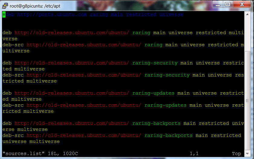
root@g8picuntu#  vim /etc/apt/source.list

4.1)  Update the package
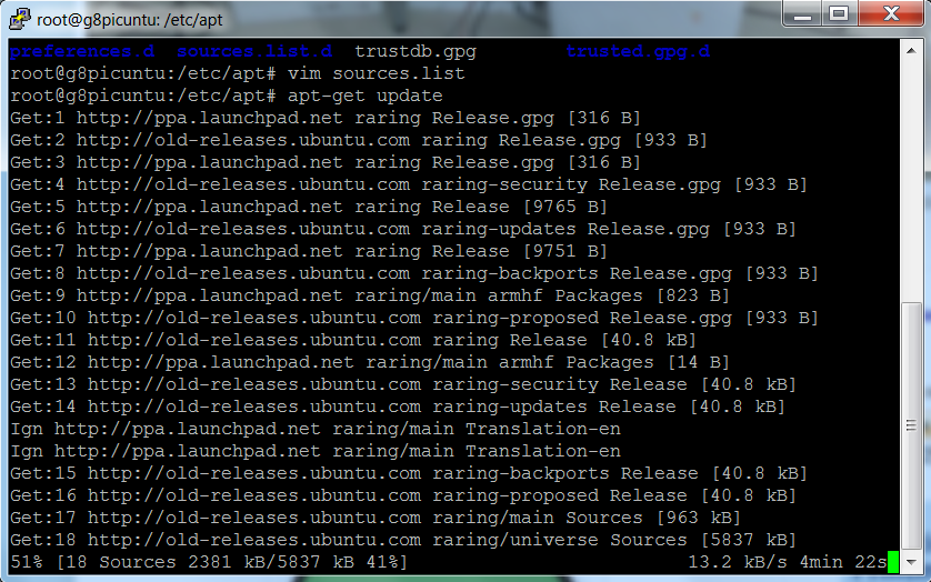
root@g8picuntu# apt-get update

5) Install Apache2, Nginx, Php5 and Mysql

root@g8picuntu#  apt-get install  apache2 ,nginx,, mysql-server libapache2-mod-php5 libapache2-mod-rpaf php5-mysql php5-curl php5-gd php-apc php5-mcrypt


6.) Checking access through vnc
root@g8picuntu#  apt-get install tightvncserver
root@g8picuntu# tightvncserver
password: "your password"

6.1)  Access IP-address of client PC ,examples 192.168.1.15:1

7 ) Test sample program and lets get back to usual setting of an ordinary Linux box
root@g8picuntu# cd /var/www/

Details:

Details:


Details:


Details:


Summary:


Conclusions:


Wednesday, February 26, 2014

Minix NEO X5 booting in Linux(Ubuntu)


Minix NEO X5


Introductions:
A couple of weeks  ago ,I've noticed  that a NEO X5 tv was still left unbox in the other corner of my cabinet ,so  I  sat down  with my stuffs in my workbench and had a harder time   of cracking  Minix Neo X5 to function in Linux -Ubuntu.As what was expected,I should  published blog  before another Internet TV box  will be ported in Linux OS(seemed I was obligated-huh!). Well, this could be  a matter of re-orienting  my e-hobby as I am rushing time for an activity which is so important than doing  this one(itanung nyo na lang kay Igorota).But  still, I decided to get all the bunch of paraphernalia -and there you have it now,a new cracked Linux OS for TV Minix box .

Actually it's a sort of personal desire ,as I  want to do the cracking  entirely  in Linux (pls. no windows) , and its hard to find a complete DIY of  booting  Minix  box solely in the said  platform  .So I started looking for a rkflashtool (Rockchip Flasher  tools   and  firmware) that could be flashed  into its  NAND memory of Minix NEO X5 .As usual,the technique is   to modify the code  by first finding   usb ID address  referring to the  dual-core RK3066(this time the NEO X5) ,then changing  the line parameter of rkflashtool.c  is required .Additional info is the filesystem used to have the Minix boot to both ubuntu and customized Picuntu .

This scratch article will discuss the boot process used on the Minix Neo x5, and some  formats/contents of each NAND (aka ROM) partition.In this way,we  can understand or manipulate the configuration of its build. Other geeks have a make up new 'rom's for the systems and produced these '.img's (recovery), and  the documentation is here  for those who want to get in on the cracking.

From the RK3066 Tech Ref Manual , the RK chip has a boot ROM and some default operations to look for suitable boot partitions on NAND and SDcard devices to power up things. Also, the boot code able to load the kernel and some root filesystem to start running OS. The system, cache, userdata and user are normal linux filesystems which can be done by mounting them in the SD card, boot is a compressed bootloader code, kernel is the binary executable loaded and executed, recovery for an option of dual OS loading (Ubuntu/Android)

Again, I would like to thanks the following geeks on the Cyber Web : view wizard,jps,olegk0,AndrewDB,Elona Dika and others for their contributions of booting NEO X5 in linux.This scratch article aims to share  anyone  the procedures ,source code, or a replacement build for the NAND partition images.

..............................enjoy the box build!   -E^3

Requirements:
Hardware:
Minix NEO X5
PC running in Linux
OTG USB cable

Software:
Linux OS installed in your computer

rkflashtool
https://github.com/linuxerwang/rkflashkit

Ubuntu OS for the Minix NEO X5  
https://googledrive.com/host/0BztHRbE8mM49TDc3WW1wMERUUkk/Ubuntu12.10_armhf_MINIXx5_CLEAN_ver0.1.tgz

Picuntu OS for the Minix NEO X5
http://cdn02.arctablet.com/mirrors/picuntu_home-io/

recovery image
https://googledrive.com/host/0BztHRbE8mM49TDc3WW1wMERUUkk/recovery.img

Objectives:
To install and boot linux(Ubuntu)  in a Minix NEO X5
To enhance linux application using Minix NEO X5
To use Minix NEO X5 in a lowcost embedded computing projects

Methodology:

Step1: Flashing the firmware  of  Minix NEO X5
1) Find the necessary tools for flashing   firmware image in the SD card
root@locahost# wget 
https://github.com/justgr/arnova-tools/blob/master/rkflashtool/rkflashtool.c

2) Install the required USB software libraries in Linux OS
root@localhost#   sudo apt-get install libssl-dev libcrypto++-dev

3) Press down the recovery(reset)  button using a paper clip or pin that can eject/push switch inside the tiny hole.

4) Power up the RK3066 device from only the OTG port using a standard usb cable

Note:
(special OTG cable required or shorting of the sense pins)
Please plugged the OTG-USB cable into your PC (running linux.)

5) After 5 seconds release the button; at this point check USB properties.
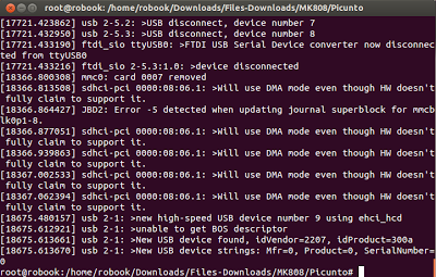
Run dmesg as you should see something liked  detail 1


root@localhost# dmesg

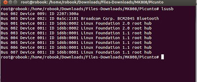
6) Run lsusb and make note of the device id
root@localhost# lsusb
My Minix NEO X5  vendor ID is 2207:300a

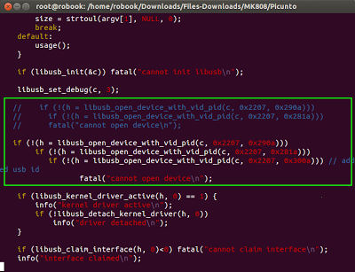
7)A vendor ID should be inserted in rkflashtool.c  as  liked in detail 2
root@localhost# tar -zxvf rkflashtool.tar.gz 
root@localhost# cd rkflashtool/
root@localhost# vim  rkflashtool.c

8)Let's compile the rkflashtool.c using gcc
root@localhost#gcc -o rkflashtool rkflashtool.c -lusb-1.0 -O2 -W -Wall -s

Note:
We're now ready to read the flash(a moment of truth :) ).
As a first step you may dumped the entire 8GB NAND flash as a backup like so


9)To backup the whole NAND-it will take sometime.
root@locahost    rkflashtool r 0x00000000 0x01000000 > myflashbackup.bin


To quickly get an idea of where everything is in the flash you can run CLI command below . It will reveal the parameters which include the offsets for all images in NAND including boot, system and  user.
root@localhost# hexdump -C myflashbackup.bin | more

10) To grab the kernel do the following:
root@localhost#    rkflashtool r 0x00004000 0x00004000 < minixkernel.img

11) To upload a new kernel do the following:
root@localhost#    rkflashtool e 0x00004000 0x00004000
root@localhost#    rkflashtool w 0x00004000 0x00004000 < recovery.img
root@localhost#    rkflashtool b

12) To have a dual booting with Android or Linux
root@localhost#    rkflashtool w 0x10000 0x8000 < recovery.img
root@localhost#    rkflashtool b


Step2:Partitioning the SD Card
Partitioning your SD Card
root@localhost# sudo apt-get install gparted*
root@localhost# gparted

1) Create an "ext4" partition
2) resize the partition atleast 5GB or larger
3) label it with "linuxroot"
4) Downloaded  and untar file from the site
root@localhost#  tar xvzf /PATH/ubuntu/picuntu.tgz  -C  /media/linuxroot/

Step3:Installations and booting
1) For wired network
root@localhost#  nano /etc/network/interfaces

2) For wireless  uncomment wireless network ,and in wpa-ssid  put the name of your network and pasw
 root@localhost# passwd dfasdf
 root@localhost# iwconfig 
 root@localhost#  reboot

3) Install Xubuntu interfaceroot@localhost# sudo apt-get update
root@localhost# sudo apt-get install xubuntu-desktop

4) Install Gnome interface
root@locahost# sudo apt-get install gnome

5)  Creating  X11 folder
root@localhost# sudo mkdir /media/linuxroot/etc/X11/xorg.conf.d/
root@localhost# cp -r /PATH_TO_FILE/exynos5.conf
/media/linuxroot/etc/X11/xorrg.conf.d/

6) Get the  exynos5.conf file
root@localhost# wget  https://www.dropbox.com/s/locvo5eotzxjg13/exynos5.conf

7.Start Minix and enjoy the interface
a) Ubuntu
username: ubuntu /password: ubuntu
username: root/password: 1234

b) Picuntu
username: root / password: 12qwaszx
username: picuntu /password: 12qwaszx
MySQL username: root /password: 12qwaszx

Details:
Details(1)Please run the lsusb command


Details(2)After finding the vendors ID ,copy the highlighted code in the rkflashtool.c


Details(3)Next run the dmesg command  to find vendors ID


Details(4) Linux logo indicates kernel proper loading


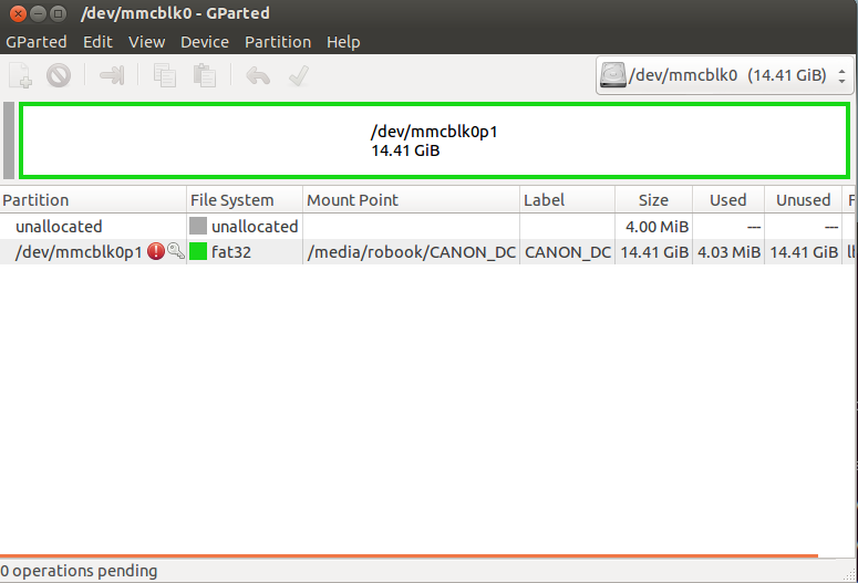
 Details(5) Partitioning SD Card using gparted command


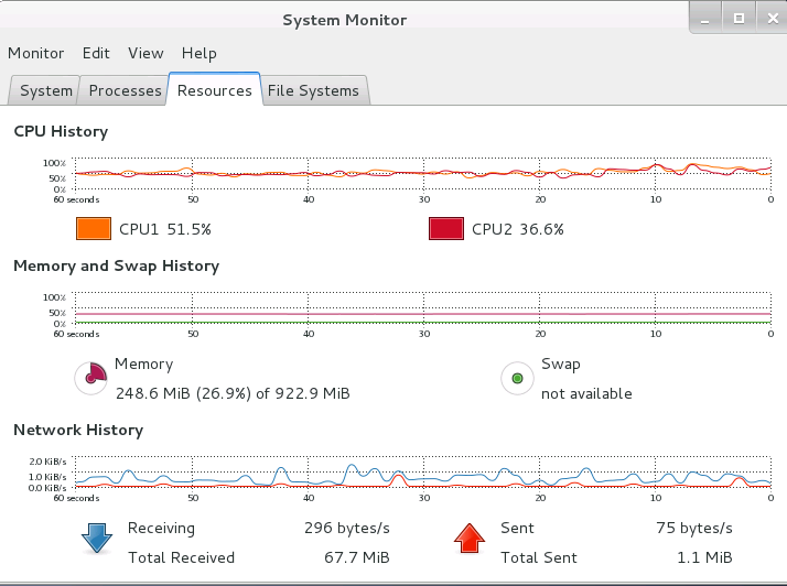
Details(6)CPU processing


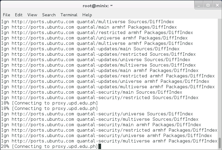
Details(7)Completing the package installation
 

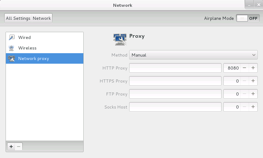
Details(8)Setting proxy


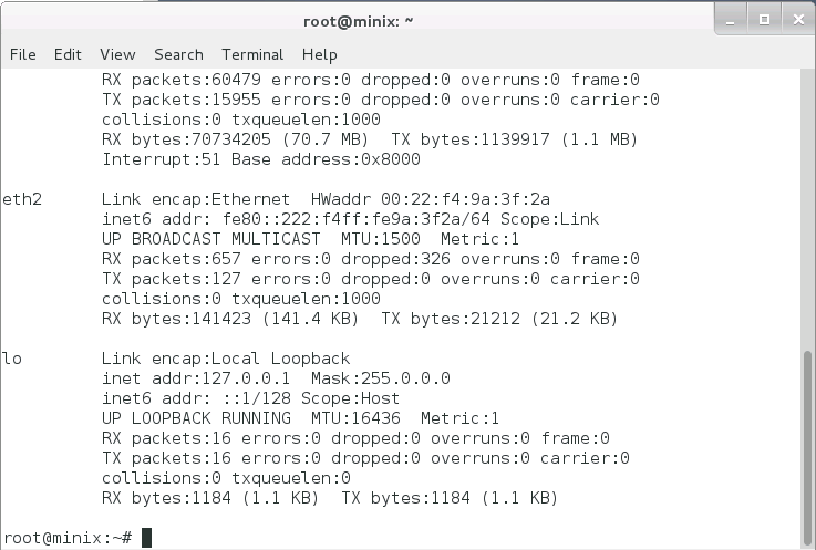
Details(9) IP address configuration (Wired /Wireless)


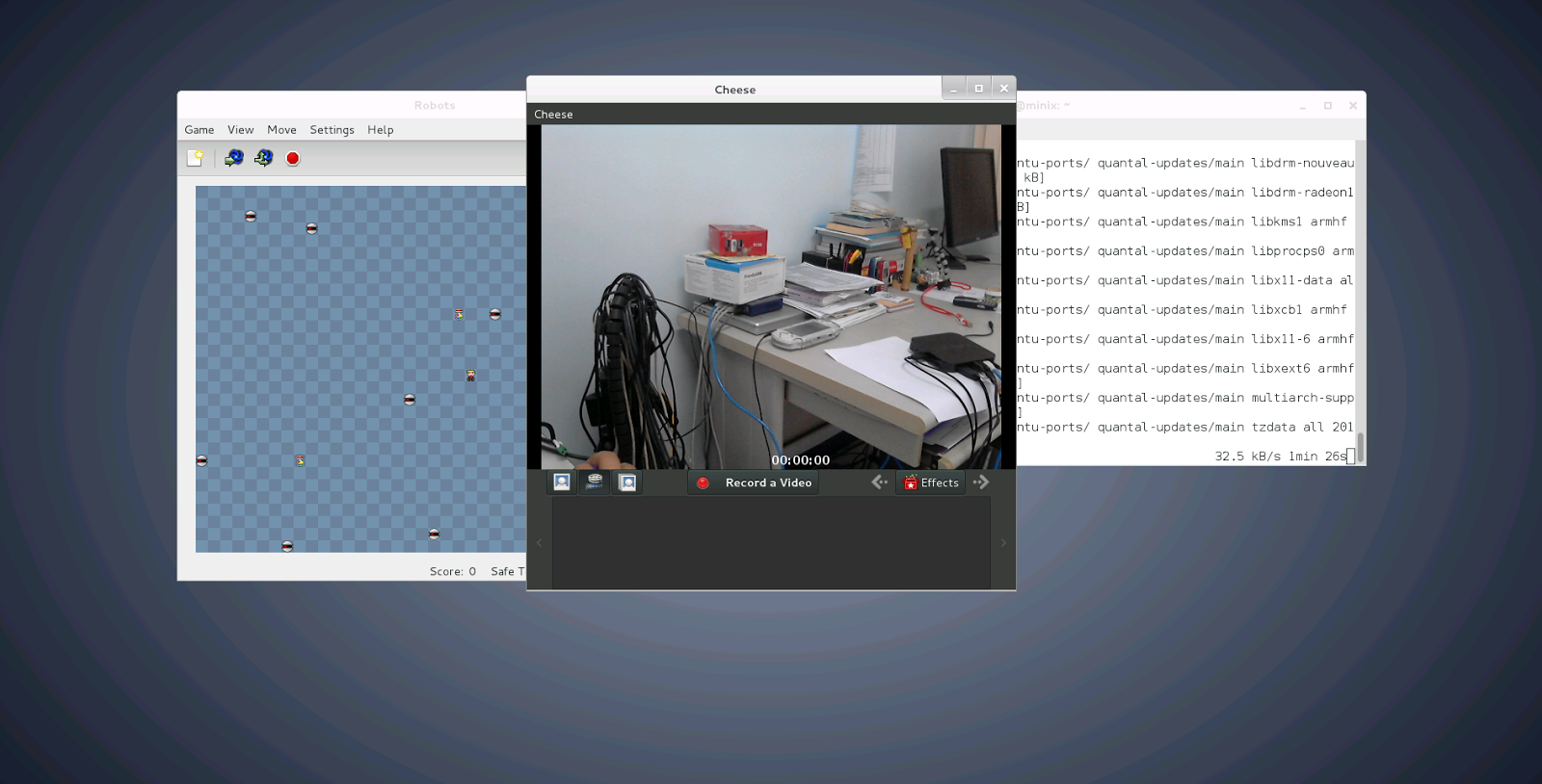
Details(10)Minix NEO X5 Desktop (Gnome)


Details(11) Running application in the box


Summary:
1) Need to enhance 2D/3D graphics accelerations


Conclusions:
This concludes that booting and running Linux in Minix NEO X5  equals  computing performance of  a traditional PC but differs in power consumptions .Another is the flexibility and robustness of the box   yet with an affordable  price as compared to any thin clients or single board PC .