Thursday, December 1, 2011

ARM11(Tiny6140) Embedded Board Linux Setup


Introductions:
Hello Technos!

Next step is to reload a new Linux distro in the Tiny6140 board.Sad thing to tell was that all the documentations were  written in Chinese language(that's I think- how I ventured to its lesser price/cost).Anyway , Google is there for the translations and firefox add-ons was able to decode whatever Chinese encoding format available  as a text inputs. This is a little bit tricky and cracky  that I need to rely in free e-books available on the net.Most of the docus' are based in ARM9 but not in an ARM11 architecture, though I need to get it done as soon as possible.

However, I've found out that some binary compiler may  work  in ARM9 as well as in ARM11 architecture ,yet others soft-apps may not ie; kernel ,loader and partition formatter .So then I referred to those images and  binaries that functions to both boards (gcc, ,tar ,bin's and etc.).

As usual  here are the steps and details(have fun!)

Requirements:
Softwares:
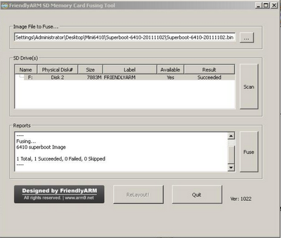
Linux or Windows XP- use either software
SD flasher -making boot loader binaries bootable to SD card
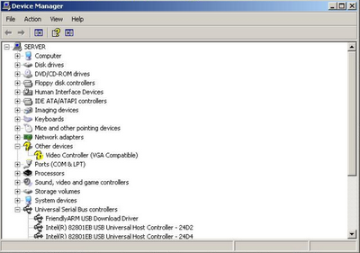
USB driver -so that your PC will recognized the board USB port 
DNW virtual- USB console
superboot20110826.bin -bootloader
rootfs_qtopia_mcl2.ubi   -partition formatter
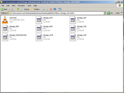
zimage_vga1024x768.bin -kernel

Hardwares:
Tiny6140 (ARM11) -embedded board
usb cable -interface to shell of Tiny6140
serial cable-interface as access to USB link by DNW


Objectives:
1) To install Linux in ARM11(Tiny6140) embedded board
2) To boot Linux OS in a NAND Flash (ROM) of an ARM11 target board
3) To simplify a hardcore embedded board set-up

Methodology:
1) You must have downloaded all the software required

2) Configure the serial com in your PC ("HyperTerminal) ,
2.a)Program->Accessories->Communications-HyperTerminal
2.b)setting are : 11520,8,N,0
2.c)you should see the virtual COM (HyperTerminal) display is responding to the character as output of the Tiny6140 board 

3) Install the USB driver for  the Tiny6140, the reason is for your board be detected by the PC-now you have 2 access in your PC via serial and via USB.

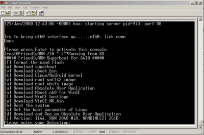
4) In your PC HyperTerminal should display options:

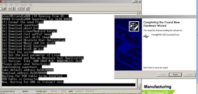
4.a) First,press "p" to load the superboot loader , the board will call the DNW to transmit the superboot(superboot20110826.bin) binary(you should kept that huh?)

4.b) Then, press "k" to load the kernel(zimage_vga1024x768.bin) , the board will call the DNW to transmit the kernel image (you have there for LCDs and VGAs image-find it!).

4.c) Then press "u" for ubi format of your board disk partitioning(rootfs_qtopia_mcl2.ubi ) , the board will call the DNW to transmit the qtopia UBI binary image.

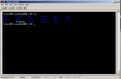
5) You should see the rolling characters , until you will stumble to the prompt asking you to press in any keys for it to display the console(shell)

6)  Turn off the board , then switch S2 to NAND booting

7) That is it, Tiny6140 board  will now proceed booting via NAND flash.

Details(1)Downloading kernel images


Details(2) SD flasher detecting the SD card


Details(3)After  by superboot format ,options prompt appear during boot up


Details(4)Included USB driver (installed usb_driver.zip) Windows "Device Manager"


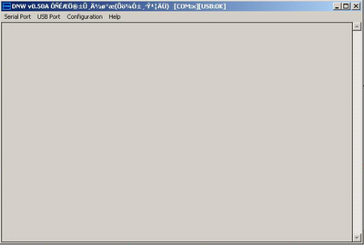
Details(5)DNW called by the Tiny6140 board(detected USB)


Details(6)DNW [OK] ready to transmit bins and images


Details(7)Flashing the NAND memory


Details(8)Almost finished loading


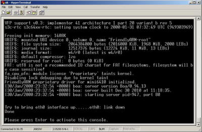
Details(9)Finally the Tiny6140 shell appear-and were done!


Remarks:
1)Next , booting Android/Linux/WinCE/Ubunto OS to the Tiny6140 board
2)As simple as that hardcore embedding

Conclusions:

Thursday, November 24, 2011

ARM9(mini2440) Embedded Board Linux Setup


Introductions:

After of a long vacations such as holidays, calamities (storm,floods or etc), we're always caught by surprise  about  the drained batteries ,damaged UPS ,hanged servers , overheated power supplies and worst the total malfunctions since the air-conditioning system had been off. The reason was just that we can't anticipate  these occurrence or technical troubles in the 24/7 running Data Center-everybody is on leave and nobody is to blame.Yet,the most things we are worried so much are the cost of purchasing  the replacements for the said equipments ,and that mishap requires a lot of budget requisitions.

So your author decided to design a complete robust yet low cost  Data Center Monitoring System .It will diagnose every client/s and server/s net activity both its hardware and software, the AC connections (power supplies and the DC generator) .It will include monitoring variable parameters such as : smoke,humidity ,temperature and noise inside the server room. The monitoring report would be available via GPRS ,GSM and web, and there is a restrictions to interact the said system.

The second option is whether to use a single board PC(ARM9) or a micro controller (PIC +ENC28j60) .So we needed to weigh the following factors: cost,capability and efficiency , and the choice went to a single embedded PC which is the Arm9 -because of the technology competitions nowadays its price is almost equal to a micro controller yet the capacity had an amazing difference.

So before the author would post in the design of monitoring system , let us first discuss the detail on the Arm 9 board set-up-and here is the detail .
 

Requirements:
Hardware:
ARM9 Evaluation Kit (Samsung chip
-533-633Mhz
Serial Cable
ARM9 JTAG
LCD2VGA 

Sooftwares:
Linux OS (Ubunto ,Fedora ,CentOS)
minicom
ztelnet
Gambas2 

Objectives:
1) Load a bootloader to a target Arm9 board
2) Load a kernel to a a target Arm9 board
3) Load applications to the Arm9 target board


Methodology: 

1) Please do the basic physical setup of ARM9 evaluation board
a) serial cable
b) LAN RJ45 

2) Download  the required software for accessing the board
a)minicom for serial/com  access
b) ztelnet for telnet setup

3) Select "b" in the menu to boot the board in RAM

4) Configure the "eth0" IP setting similar to your LAN
root@FriendlyArm/  cd /etc/
root@FriendlyArm/  cp  eth0-setting eth0-setting.bak
root@FriendlyArm/  vi etho-setting 

5) Explore files in the Arm9 linux shell

 Detail(1) minicom serial interface for Linux

Detail(2) Configuring the minicom settings

Detail(3) Detecting Arm9 via serial com

Detail(4) booting Arm9 via NAND flash
Detail(5) Setting the board's  IP address

Detail(6)Browsing the Arm9 default page


Remarks:
Its another refreshing ideas to level up embedded applications,especially when times suggest a better competitions between a traditional micro-controller/microprocessor and a single board cpu , its  cost, efficiency,capability and rigidity.

Conclusions:


Wednesday, May 4, 2011

CHDK reInventing Canon Camera

Introductions:
This tutorial will be dealing about the hard core of hacking Canon Cameras. Some technique or reverse engineering will be explained how signals are turned into a parsed data and the combinations that lead to the analysis of protocol behind the original Canon Firmware.

Here we explain and give understanding :

How hacking is done in Canon?

How signals are decoded and converted into a data

How data are analysed as format of protocols

Its preamble?

Its ports addresses?

Its acknowledge data

How data is checked and evaluate
CRC and checksum

and so forth..


Requirements:
Canon Cameras
LED,Photo Diode
DB9 serial Comm port
Microphone (sound into waves)
Oscilloscope


Objectives:
1) To explain How hacking is done in Canon Camera
2) How to bypass the original Canon Firmware using CHDK scripts
3) To give an example of reverse engineering Canon PowerShot G11


Methodology:


Remarks:


Conclusions:

Friday, April 15, 2011

Canon G11 Remote Capture (CHDK)


Introductions:

This is a little bit article to investigate how we can change a Canon G series features,since Canon Company had stopped supporting the remote triggering of its Powershot G series a lot of of hobbyist, hackers and enthusiast are finding ways to resolve this issues or on the other hand their efforts are to indigenously improve and extend their cameras' shooting capabilities.

In our case ,since there are 2(two) available pairs of G11 in the laboratory and want them to be used in book scanning , hence a remote triggered must be one of its features and so the solutions is to look for an alternative hard coded software that will bypass Canon camera firmware and therefore extends its features in some ways.

Well,I have these ideas in mind:

(One)Get the latest CHDK for G11 that supports USB/PTP or (Two)Load the alternative firmwares SDM scripts; then on the PC side use the gphoto2 and Gambas2 would intervene the whole process (as plugging ON and OFF the USB) .And instead of a mechanical switch I'll try to use micro-controller interface to USB for a camera access while in the process upload a captured images in the SD Card .

I have some reference to follow.
Good article for remote capture using CHDK /SDM (by: Tom Horsley)
http://home.comcast.net/~tomhorsley/hardware/scanner/software.html
CHDK site
gphoto2 site
SDM site
well again lets include gambas2


Requirements:
Camera Version Finder
http://savedonthe.net/download/247/CameraVersion13-sfx.html
CHDK firmware port to G11 version 100l.
http://chdk.setepontos.com/index.php?topic=4647.510

SDM
Gphoto2
Gambas2


Objectives:

1) Extended G11 (Canon Powershot G series) extended its shooting mode features and capabilities
2) Get G11in RoBook Scanning task.

Methodology:

1) Get SD Card
Note:
If the card is 2GB you can partition it directly , however when the capacity is much larger you can partition it into two , the other space is for booting while the other one is for CHDK files.
1.1) root@localhost # df -h
1.2) root@localhost # yum install gparted

2) Click " Applications" menu
2.1) Click System Tools
2.2) Click gparted
2.3) Enter your root password

3) Formatting SD card 2GB partition into FAT16

4) Make the SD Card bootable

5)For Auto-loading the CHDK scripts lock the SD Card

6) Insert the SD Card in the Camera then turn ON

7) You will see the image appearing as shown in "Detail(5)".

8) Debugging the USB/PTP script(at our own risk!)

Detail(1):Camera Version With G11 capture photos


Detail(2):Camera Version Finder


Detail(3) Generated camera version from an image files


Detail(4) Gparted partitioning SD Card


Detail(5) : Card Trick FAT16 format on SD Card


Detail(6) Formatting card into FAT16


Detail(7) Canon G11 is now Hacked!


Remarks:

As I've mentioned a while ago , I have two ideas in mind :
The first is the USB/PTP encoded in CHDK but need to wait first for the hacking release ,Yet a Canon SX200IS had the code ported already so possible for the Canon G11 also.Whatever, the other method plugging in /out or switching ON/OFF will be much more easier to accomplished for now compared to the latter method(we'll see if there's a ported code already for G11).


Conclusions:
Still on going

Monday, March 7, 2011

Pinguino (USB to PC interfacing)


Introductions:

This is a parallel task with my RoBook Scanner, I am using this development to control motors installed in a Robot Arm.An IDE of a RoBook Scanner is installed in the computer and its communications is trough USB. A PIC-USB then will be very helpful and adequate for our requirements .Another,it should be running in Linux with a pre-build drivers in com port.This simple system is expected to have an easy work flow every time the scanning event occurred ,there would be a corresponding status sent to a microcomputer to trigger its I/O ports from turning the motors .Hence ;the robotic arm will respond in accordance to the program flow and there will be synchronizations of task in the RoBook Scanning system.

I browse at e-Gizmo central ,I don't have time to assemble it on my own: PIC18F455,USB, Oscillator ,circuits then PCB, ok, gizmo is there!So I call them up and order it via western union(that's it) .I just need to focus merely in our development ,don't care to bother assembling it -gone are those days(you know!) .

Okey, so what's Penguino?
Penguino is a PIC184550 USB development board which is running in fully Opensource tools pioneered by a French electronic engineer one of the main purpose is to have a useful application in the academic institution and a hacking lab for a hobbyist

Objectives:
To create libusb application program , either by thread or coroutine(scripting).
To communicate PC and micro-controller via USB (host & device).
To apply USB interfacing in our RoBook Scanning.

Requirements:

Software:

Ubunto Linux OS ( Ubunto-10.10)
libusb
penguino(linux)
-sdcc
-gputils
-gmasm
LUA(C scripting language for embedded)
Python and libraries:
python-wxversion
python-wxtools
python-wxgtk2.8
python-wxgtk2.6
pySerial (Python serial module)

bootloader for PIC184550 (http://www.hackinglab.org/pinguino/download/latestfirmware/bootloaderV2.12.hex)

Hardware:

Penguino development board
Desktop/PC

Methodology:

1) Software downloading ,compilations and installation
2) Penguino setup (adaptor, USB cable and Pinguino board)
3) Loading the boatloader hex file for PIC184550 mcu.
4) USB host program in Pinguino IDE
4.a) Select sample code for LUA
4.b) Select sample code for libUSB
5) Device /client USB ID (CDC) program to PC (where Pinguino IDE is running)
5.a) Sample USB terminal (using Pyserial)
5.b) Pinguino sample code on USB hosting.


So here we go...

Installing Python
root@localhost# sudo apt-get install python

Installing LUA
root@localhost# wget http://www.lua.org/ftp/lua-1.0.tar.gz
root@localhost# tar -zxvf lua-1.0.tar.gz
root@localhost# mv lua-1.0 /usr/local/lua
root@localhost# cd /usr/local/lua
root@localhost# ./configure
root@locahost# make
root@localhost# make install

Installing LUA-libraries
root@localhost# wget http://luaforge.net/frs/download.php/4252/lualibusb-0.4.tar.gz
root@localhost# tar -zxvf lualibusb-0.4.tar.gz
root@localhost# cd /usr/local/lualibusb-0.4
root@localhost# ./configure --prefix=/usr/local/lua
root@localhost# cd liblua/
root@localhost# vim Makefile
Then change the following line with your liblua PATH=?
LIBUSB_SRC = /usr/include/libusb-1.0 #change with your libusb sources folder
LUA_SRC = /usr/include/lua5.1 #change with your lua sources folder
root@locahost# make && make install
Find lualibusb.so
root@localhost# ls lualibusb.so
If the file is there then rename this file to libusb.so copy it in "/usr/local/liblua/lua5.1/"
root@localhost# mkdir /usr/local/liblua/lua5.1/
root#localhost mv lualibusb.so /usr/local/liblua/lua5.1/libusb.so

Lua add-ons libraries

root@localhost#sudo apt-get install liblua5.1-0-dev libusb-dev libreadline-dev

Installing Pyserial
root@localhost# sudo apt-get install pip-python
root@localhost# sudo apt-get install python-serial

Installting Penguino USB Terminal
root@localhost# wget http://sites.google.com/site/pinguinotutorial/lua-usb-terminal/pinguinoUSBterminal.tar.gz
root@localhost# tar -zxvf pinguinoUSBterminal.tar.gz
root@localhost# cd pinguinoUSBterminal
root@localhost# ./configure --prefix=/usr/local/usbterminal
root@localhost# make & make install

Installing Penguino
root@locahost# wget http://www.hackinglab.org/pinguino/download/pinguino%20beta%209/pinguino_beta9-05_linux.tar.gz
root@locahost# tar -zxvf pinguino_beta9-05.tar.gz
root@localhost# mv pinguino_beta9-05 /usr/local/pinguino
root@localhost# cd /usr/local/pinguino/
root@localhost# pythton pinguio_beta9-05.py

Detail(0) Getting the necessary libraries for pinguino


Detail (1) Installing and compiling Pinguino


Detail (2)Pinguino Graphics IDE


Detail(3)Pinguino Editor


Detail(4)Development board fron e-gizmo store


Detail(5) Start of cloned Pinguino board setup


Remarks:
Note:
The Pinguino picture that appears above came from the e-gizmo website(Please support "Ang galing ng Pinoy")


Conclusions: